
Tags
analog, audio, digital, MEMS, microphones, PDM, Pulse Density Modulation
This is the first of several articles on the general subject of audio signal processing, starting at the interface between sound and electronics: the microphone.
Future articles will demonstrate some unusual approaches and platforms, and show off some applications.
MEMS Microphones

(Photomicrograph courtesy of Chipworks, as seen in MEMS Journal)
Microelectromechanical systems (MEMS) technology has allowed the creation of many interesting devices that previously would have required substantial mass and volume to implement. By sharing the same fabrication technologies used to make integrated circuits, MEMS devices can have both moving parts and electrical components, and with care can even include significant amounts of integrated circuits to provide for signal conditioning and other functions within the same package as a sensor.
As MEMS technology matured, so did the need for ever more compact devices. A typical smart phone contains MEMS sensors for both linear and angular acceleration, magnetic fields, often barometric pressure, and even audio.
MEMS allows a microphone to be built at chip-scale, with a membrane only a millimeter or so in diameter, and with the most sensitive of the needed analog electronics sharing the same package. Recent advances allow the conversion from analog to digital to move into the microphone package as well.
Digital MEMS microphones are quite inexpensive to make. A typical example is made by Knowles, provides a serial digital signal, is less than 5 mm long by 4 mm wide, and a little more than 1 mm thick, in a 6 pad surface mount package, and sells1 for around $0.85 each in 1000 piece quantities.

The Knowles microphone has an open port (just under 1 mm in diameter) for sound to enter. The port location is either on the top or bottom face of the package, and the selection of that port location must be made in concert with the mechanical design of the device packaging so that the port can face in a useful direction.
Behind the port and a debris filter is a silicon wafer with the sensor membrane constructed by micro-machining techniques. The membrane forms a capacitor with the base plate behind it. Variations in air pressure (also called sound waves) move the membrane, causing variation in the capacitance, which is sensed, amplified, and processed by circuits on a second die in the package.
While electret capsule microphones can be made to approach the volume of a digital MEMS package, they are not price competitive at that size. At sizes where they are competitive in price they are much larger, plus they require analog signal conditioning and conversion to digital to be done externally to the microphone package.

Besides the obvious advantage of occupying less volume than conventional microphone elements, the digital MEMS microphone also provides better isolation from nearby RF signals (as from a cell phone transmitter) and simplifies the electronic design by reducing the required supporting circuits to just PCB traces for clock and data, power supply, and a configuration pin that allows two microphones to share the same clock and data for stereo applications.
The small size and all digital interconnect comes at a price. Instead of analog signal conditioning circuits and an audio-rate ADC, one has a much higher bit rate serial signal that requires digital signal processing to recover the audio signal. Nevertheless, the advantage is clear: If the most noise sensitive parts of the audio input stages are small, well shielded, and isolated from the rest of the phone, then the digital audio stream can be higher quality for a particular size, weight, and volume budget. Moreover, as microcontrollers have advanced in processing power even as they decrease in cost, the advantage of an all-digital connection increases. Current generation microcontrollers, if carefully coded, can perform the required signal processing in their CPU core, without requiring a separate DSP core.
PCM and PDM signals
Sound is transmitted from a source to the listener by small, rapid variations in air pressure. In simplest possible terms, the amplitude of the variation relates to the loudness of the sound, and the rate at which it varies relates to the pitch of the sound. (I’ve left out almost all of the science of acoustics in that explanation.)
 (Photgraph by Patrick Bombaert, used under the terms of the Creative Commons Atribution 2.0 License.)
For analog recording, all that is required is to transcribe those variations in pressure into some other medium. For playback, you simply reverse the process to recreate varying air pressure. In the toy made from two tin cans and some taut string, the first can’s bottom senses air pressure changes and vibrates the string, which pulls on the second can’s bottom to move the air in the can. A phonograph replaces the string with a groove in wax or plastic, a simple phonograph can actually be made from a pin and some paper. (Don’t use it on valuable recordings!)
For digital recording all we need to do is capture the pressure level as it varies and transform it to a sequence of numbers. For digital playback, those numbers can be converted back to varying air pressure.
The sequence of numbers that represent the air pressure at each moment of time is called PCM (Pulse Code Modulation) audio. To reproduce a sound with good fidelity you need to sample it often enough, and with enough precision. Audio CDs sample each channel with 16 bits of precision, at 44100 samples per second (44.1 kHz). The telephone system generally samples audio at about 12 bit precision (another over-simplification, but aLaw and muLaw aren’t important here) at 8000 samples per second.
But 12 or 16 bit precision can require lots of parallel wires, or it can require complicated serial protocols. Multiple parallel wires require more package pins and introduce synchronization requirements. For cell phones and hearing aids, there is a lot of market pressure for everything to get smaller and more reliable so a serial connection is indicated.
There is a well-established serial protocol for sound data called I2S (sometimes written I2S or IIS), which uses a data wire, a bit clock, and a frame clock to convey pairs of PCM samples. It works well for some applications. But using it for a microphone would have the disadvantage that it would make the entire signal quality depend on the algorithms baked into the chip inside the microphone package.
Most digital MEMS microphones take a different approach: they provide a much higher sample rate at a much lower precision, which moves most of the parts of the signal processing that directly impact the sound quality into the receiving device and out of the microphone’s package while still providing a digital interface. That signal is called PDM (Pulse Density Modulation).
PDM represents the position of the diaphragm (which is proportional to the instantaneous air pressure variation) at each sample by the probability of the sample being 1 or 0. A dead silent room will produce a stream of alternating 1’s and 0’s. If the microphone’s sample rate is 2.8224 MHz (exactly 64 times the sample rate of CD quality audio) then a 1 kHz tone that is fully clipped (slamming the diaphragm into its physical stops, and possibly about to destroy the microphone, not to mention the hearing of anyone nearby) would appear as about 1411 1’s followed by about 1411 0’s in a repeating pattern.
From PDM to Audio
Creating a PDM bit stream from the analog measurement of the membrane’s position is a well understood design problem that is closely related to a class of analog to digital converters called sigma delta converters.
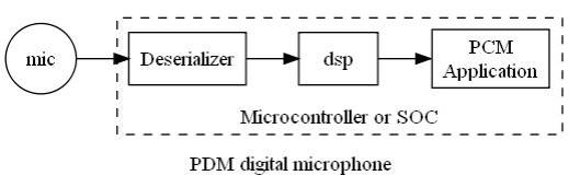
Given the high data rate PDM bit stream, recovering a lower data rate PCM stream from it is easily done by applying a suitable low-pass filter with decimation. The requirements for these filters are also well understood, and tricks are known that make it easy to decimate by a power of two using only addition and subtraction2. The usual practice for PDM microphones is to assume decimation by 64.
The Knowles microphone described expects to be clocked at any rate between 1 MHz and 3.25 MHz which when downsampled by a factor of 64 produces finished PCM audio samples at all the common PCM rates ranging from 16 kHz (1.024 MHz) to 48 kHz (3.072 MHz). If required by the telephone network, classic telephony samples at 8 kHz can be produced by a further decimation and conversion to either µLaw or aLaw representation.
In the next few installments we’ll document a stunt implementation of PDM decoding that works and produces a useful output. We’ll follow that with a more practical implementation that can serve more demanding applications.
(Written with StackEdit.)
- From the Digikey SPM0437HD4H-B product page. ↩
-
citation needed Look for a [future post][pdm-02] that shows a real implementation.
[pdm-02]: /2015/01/16/pdm-in-a-tiny-cpu/ ↩

Thanks ! This helped me a lot !!!
LikeLike