
Tags
The Raspberry Pi is an inexpensive single board computer barely larger than a credit card. It has become very popular for implementing small projects that require a controller CPU.
I had in mind using a Raspberry Pi in my home to add a garage door alert that my security system could not provide by itself. A magnetic sensor switch mounted on the garage door would be wired to the Pi, and I would write a program that could alert me if the door was left open accidentally. The Pi could send an email or text message if the door was open longer than five minutes, for example. Also, the Pi could be connected to a spare input of my home security system, and stimulate it to make the system’s keypad sound an audible alert inside the house.
So the door sensor, which is simply a switch, had to be connected to one of the Pi’s general purpose input ports in a way that causes a logic high state or a logic low state depending on whether the door is open or closed. Connecting one side of the switch to the Pi’s circuit common, and the other side to the input port causes a logic low when the switch is closed. And to get a logic high when the switch is open, a pull-up resistor is connected from the input port to the Pi CPU’s positive power supply voltage.
However, the input to the Pi should also be filtered to keep it from being affected by noise from local interference or from the switch contacts bouncing. This can be done with a simple resistor-capacitor filter between the switch and the input port.
For the input port to sense the state of the switch, the primary requirement is that the closed switch pull the input to near zero volts, so the filter resistor must be much smaller than the pull-up. The resistor values must be such that the input port goes below the CPU’s low level input threshold voltage. However, that means that with the switch closed, the filter time constant will be much smaller than when the switch is open and the filter resistor is out of the circuit. Clearly this scheme is faulty if one goal is for the filtering to be roughly symmetrical. But that wasn’t a requirement here. The minimum time constant I wanted could be accomplished with a capacitor value that gave that result with the filter resistor, and although the longer time constant when the switch is open far exceeds the requirement, the maximum is dictated by how much switch opening time delay is acceptable.
Next the Raspberry Pi had to be connected to the security system so it could signal inside the house. The security board has zone inputs that are normally closed loops. When the system is not armed, opening a zone loop causes an alert sound from the control keypad. So two things were needed. First the Pi had to monitor to security system to know when it was armed and when it was not, otherwise if the Pi opened the loop when it was armed the house alarm would be triggered. Second, a general purpose output of the Pi had to be used to open or close a zone loop input of the security system.

Raspberry Pi in upper left
The security system has an RS-232 serial interface that can be used to monitor events. Connecting that to the Raspberry Pi’s serial port through an inexpensive RS-232 to logic-level interface circuit took care of the monitoring function.
Using a Pi output port to open and close the zone input is a little trickier. Ideally, a switch is connected across the zone input. So the Pi output has to control a switch. An obvious electronic switch is a transistor. But that can only work if the Pi and the security system share a circuit common. Fortunately, one side of the zone loop input is the security system’s circuit common, so connecting it to the common of the Pi allows using a transistor to close the zone input.
Connecting a general purpose output port of the Pi to the gate of a MOSFET transistor with a logic-level threshold controls it as a switch. The MOSFET source terminal is connected to the zone input side which is circuit common, and the MOSFET drain is connected to the other side of the zone input.
But it turns out not to be that simple. The security system has battery backup in case of a power failure, but the Raspberry Pi does not. The Pi has to keep the zone input loop normally closed. If power fails, I would not want the zone to open, especially if the system were armed, for that would cause the alarm to go off. So the state of the output port that keeps the zone input switch closed must be the logic low state. It will default to that if the Pi loses power. But a high state is required on the MOSFET’s gate to make it a closed switch.
The solution is to add another MOSFET stage in between the output port and the MOSFET connected to the zone input. That inverts the logic state. It is conveniently powered by the 12 volt auxiliary supply available from the security system board.
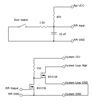
Input and output interface circuits
So, having completed my hardware interfaces between the Raspberry Pi computer and my home security system, I now have a program running in the Pi that monitors the system to discern when it is armed and when it is not, and monitors the garage door sensor to tell when it is open and closed. If the security system is not armed, the Pi momentarily opens a zone input so an audible alert is heard inside the house when the garage door opens, and also periodically if it remains open longer than five minutes. While the security system is armed, the Pi keeps the zone input closed so it does not trigger an alarm. However, in that case it sends out a text message email if the garage door has been open longer than a few minutes, and periodically if it remains open. So if we arrive home and come into the house forgetting to close the garage door, we’ll get notified inside. And if we leave the house, arming the security system, and forget to close the garage door, we’ll receive a text message before getting too far away.

Good day. I’m also using a Rasberry Pi to monitor some stuff inside my home. I like your way on how to monitor your garage door and let the alarm beep when you are inside the house. My alarm can do the same on its zone and I’m going to use your idea. Great thinking.
Some question. What programming language are you using with your Pi?
Regards
Johannes
LikeLike
I used C for the main program. And the C program calls a Python program to send email.
LikeLike